
Electronics assembly and functional test lines for PV inverters and power conversion units, from bare board to a serialised, fully tested unit.
This is equipment for manufacturing inverters. The product design, topology and certification remain yours; we design and engineer the assembly and test line that builds it repeatably, at your target volume, with full unit-level traceability.
SMT placement, reflow, inspection and electrical test of control and power boards.
Power stage, magnetics, busbars, cooling and enclosure integration under controlled torque.
Electrical safety, functional grid simulation, burn-in and end-of-line verification.
Power module clamping torque and thermal interface material coverage determine junction temperature, and therefore field reliability, more than almost any other assembly parameter. Both should be measured, logged against the unit serial number and trended in SPC, not left to operator technique.
Test capability is where inverter lines most often prove under-specified. Functional testing needs a programmable DC source and a grid simulator capable of exercising the protection behaviour your certification claims.
| Test stage | Purpose | Typical capability required |
|---|---|---|
| HiPot / dielectric withstand | Verify insulation integrity between circuits and to chassis | Programmable AC and DC hipot with ramp control and per-unit result logging |
| Insulation resistance | Confirm insulation quality before energising | Megohm measurement across defined test points |
| Ground bond / continuity | Verify protective earth path integrity | High-current bond resistance measurement |
| Functional / grid simulation | Exercise MPPT, conversion efficiency and grid interaction | Programmable DC source plus regenerative grid simulator; anti-islanding, LVRT and THD capability |
| Protection trip verification | Confirm over/under voltage and frequency trip behaviour | Grid simulator with fault and ride-through profile scripting |
| Burn-in / aging | Precipitate early-life failures before shipment | Load banks and controlled thermal chamber with continuous monitoring |
| Firmware & calibration | Flash production firmware, calibrate sensing, serialise | Automated flashing station writing calibration data and serial to MES |
| End-of-line verification | Final functional confirmation and test report generation | EOL station producing a per-unit report bound to the serial number |
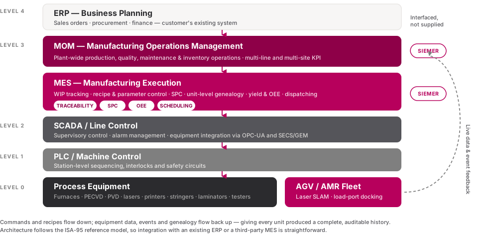
Inverters carry long field warranties, so production data is a commercial asset. Each serialised unit should be linked to its board genealogy, component lot data, torque and thermal interface records, calibration values, firmware version and complete test results.
When a field failure pattern emerges, that record is the difference between a contained recall and an uncontained one. We engineer the line so this data is captured automatically at each station through the MES layer.
Send us your target annual volume, unit power class and certification targets, and we will scope the assembly and test line against them.